 |
|
|
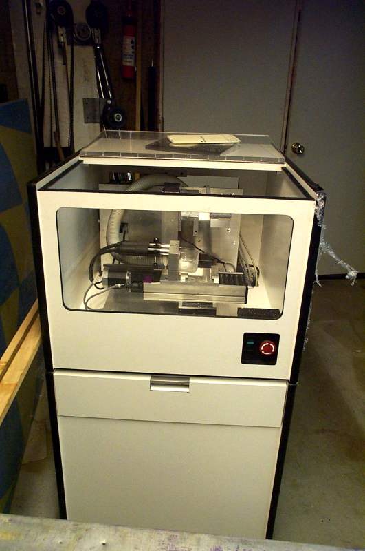
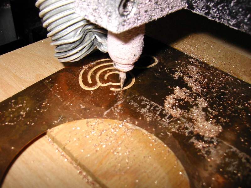
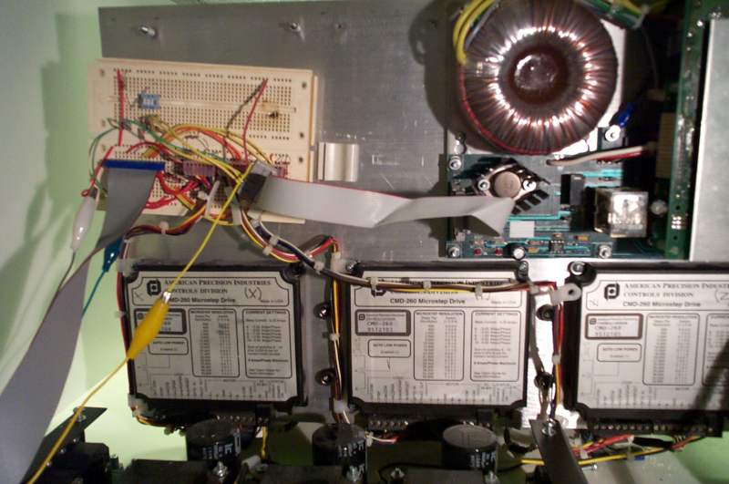
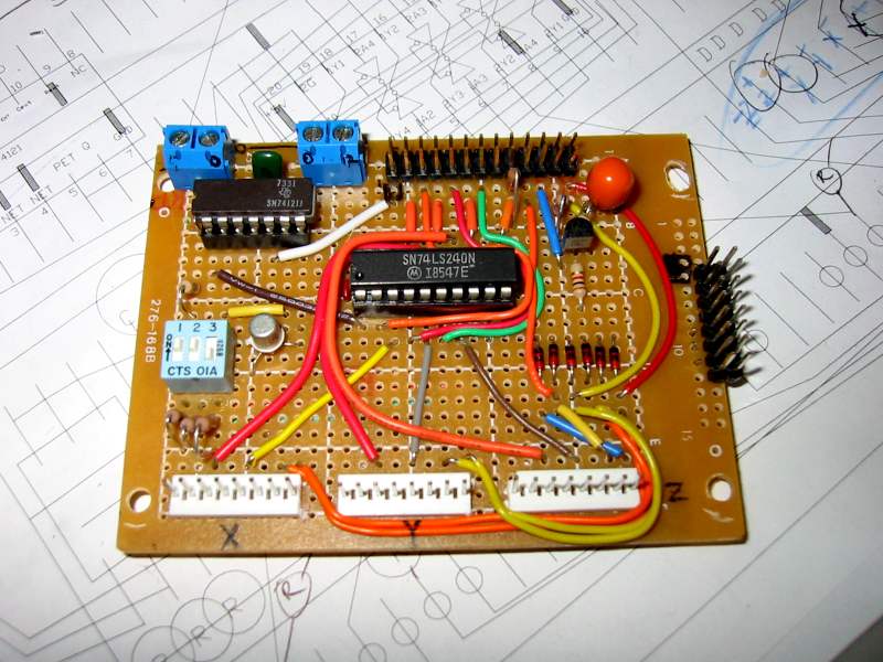
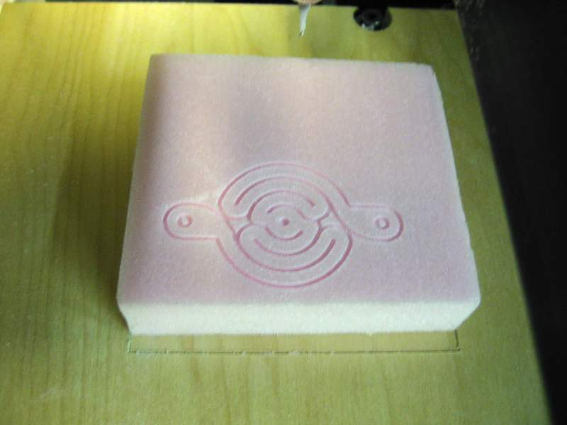
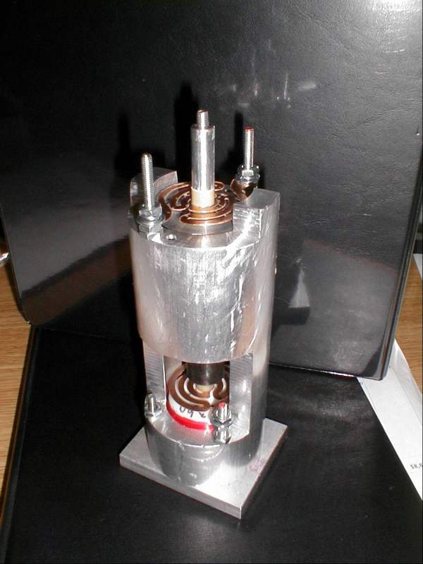
The process of converting them to classroom use began by reverse engineering the spindle control (since I was already quite familiar with the control of "step and direction" stepper drives). While I could have substituted a Dremel, it was pretty clear that the spindles (two per mill) were high-quality, brushless DC devices. After a painfully tedious process, I was able to discern the functions of all necessary leads in the 16-wire cable coming out of the spindle control board, and utilize both on/off and speed control capabilities. Having tested the spindle and three axis motion (with home and limit switches), I soldered up two permanent interface boards and modified the spindle orientation to a more intuitive Z direction. After a trip to Home Depot for some polystyrene, I started to have some fun... My first trials involved milling out the Science Museum of Minnesota's logo. Using a larger bit to do the roughing, and a 1/32" bit for the detail. (pic coming) The next step was to see whether I could bridge the 3D modeling and animation software, Blender, to these machines. Blender is powerful freeware, which is taught to students in the Learning Technologies Center at the Science Museum in their animation classes. Blender, while perhaps not the easiest package to use, is an obvious choice for novices unwilling to shell out hundreds or thousands of dollars. The idea: students create a 3D surface in Blender, then save the data in a way that can allow a toolpath to be created and fed to the mill--virtual reality converted to real reality.
To further the capabilities of these mills, I contacted the makers of Mastercam (CNC Software, Inc.). After explaining our goals, they graciously offered to donate a copy of their industry-leading CAM software. With this sophisticated package, we should be able explore far more complex toolpath options.
|
|
